Variants of pressure generation
Poppe+ Potthoff Maschinenbau GmbH
There are many different forms of pressure generation and each variant has certain advantages and challenges. We recommend a suitable pressure unit for the test requirements to our customers and integrate it into a modular system concept.
Pressure generation with a hydraulic pressure intensifier
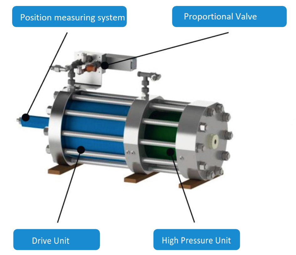
With a hydraulic pressure intensifier, the test pressure is proportionally controlled by oil. As a result, the desired pressure points can be approached very precisely. The system must also be equipped with a hydraulic unit and a cooling water circuit to generate the oil control. The pressure intensifier also acts as a media separator so that the drive medium (oil) and the test medium (e.g. water) do not mix.
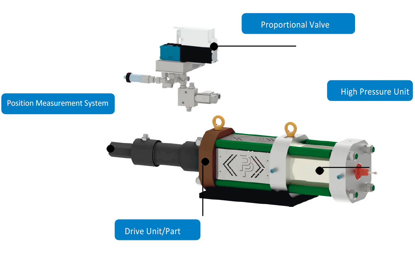
The pressure intensifier is controlled via a hydraulic proportional valve, which generates a defined volume flow in conjunction with a PID controller. The pressure intensifier consists of a drive part and a high-pressure part.
Drive Part
The pressure intensifier is moved via a linear drive part. The essential components of the drive part are a piston rod with a piston, a cylinder tube with a cylinder bottom, and a cylinder cover. To find the position of the piston, the piston is connected to a displacement measuring system. The hydraulic pressure is fed in via the cylinder bottom.
High-Pressure Part
The required test pressure is generated in the high-pressure part. The high-pressure sealing package is mounted on the piston rod. The hydraulic pressure and a defined volume flow in the drive part are guided by a control signal sent by a PID controller to the proportional valve. The power transmission in the high-pressure part is carried out via two pistons sliding in cylinders. The required test pressure is generated via the previously defined transmission ratio.
Pressure generation with a pneumatic pressure intensifier
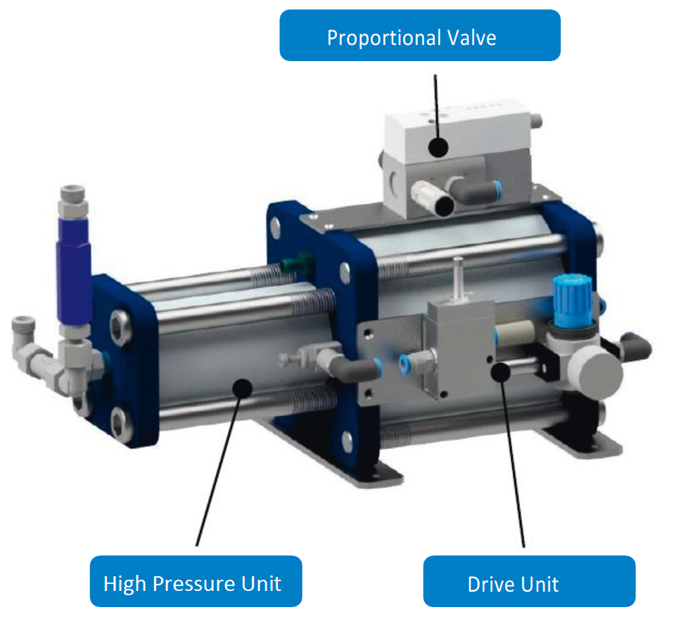
With a pneumatic pressure intensifier, the test pressure is proportionally controlled by air. This allows the desired pressure points to be approached. The regulation is carried out
via a pneumatic proportional control valve, which regulates the compressed air (up to 6 bar) to control the test medium in the pressure intensifier. The pressure intensifier also acts as a media separator so that the drive medium (air) and the test medium (e.g. water/oil) do not mix. The pressure intensifier consists of a drive part and a high-pressure part.
Drive Unit
The pressure intensifier is moved via a linear drive part. The essential components of the drive unit are a piston rod with a piston, a cylinder tube with a cylinder bottom, and a cylinder cover. In order to precisely define the position of the piston, the piston can optionally be connected to a position-measuring system. The air pressure is fed in via the bottom of the cylinder.
High-Pressure Unit
The required test pressure is generated in the high-pressure part. The high-pressure sealing package is mounted on the piston rod. By means of a control signal, which is sent to the proportional valve, the air pressure and a defined volume flow are directed into the drive part. The power is transmitted to the high-pressure part via two pistons sliding in cylinders. Above the previously defined transmission ratio generates the required test pressure.
Due to the compressibility of the compressed air, the control accuracy depends on the test object’s volume and the pressure range.
Title for This Blockext for This Block
Pressure generation with a High-Pressure-Pump
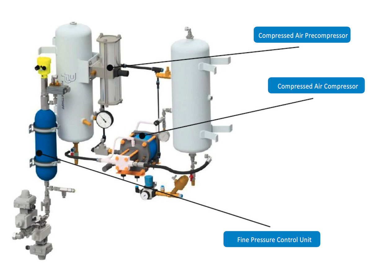
The high-pressure pump is pressurized with compressed air via a directional valve. The conveying piston is moved via the compressed air actuation piston. The amount of media in front of it is deported. Due to the area ratio of the actuating piston and the conveying piston, the pressure required for conveying is generated. The desired operating pressure is set by using a pressure reducer on the pneumatic drive side.
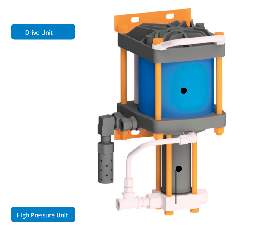
The test pressure is realized with this control method via a built-up process. Since no friction affects the control in this process as with a pump or pressure intensifier, this process is very accurate and has no wearing elements, which must be changed regularly.
Pressure generation with differential pressure intensifiers
In the case of a differential pressure intensifier, the test pressure is proportionally regulated by oil. As a result, the desired pressure points can be approached very precisely. To generate the oil control, the system must also be equipped with a hydraulic unit and a cooling water circuit. The pressure intensifier also acts as a media separator so that the drive medium (oil) and the test medium (e.g., water) do not mix.
The pressure intensifier is controlled via a hydraulic proportional valve, which generates a defined volume flow in conjunction with a PID controller. The pressure intensifier consists of a drive part and a high-pressure part.
Drive Unit
The differential pressure intensifier is moved via a linear drive part. The drive part is a hydraulic cylinder with an integrated displacement measuring system. In order to precisely define the position of the piston, the hydraulic cylinder is connected to a position-measuring system. A coupling connects the drive part to the high-pressure part. The coupling is also used to compensate for radial offset.
High-Pressure Unit
The required test pressure is generated in the high-pressure part. The differential pressure intensifier does not use a travelling sealing package, but two standing sealing packages, which carry a stepped piston. Through a control signal sent by a PID controller to the proportional valve, the hydraulic pressure and a defined volume flow are directed into the drive part. The power transmission in the high-pressure part is carried out via the coupling and a stepped piston. The required test pressure is generated via the previously defined transmission ratio.
The special feature of the differential pressure intensifier is to introduce a small volume into the DUT (device under test) but to record it over a long distance. This makes it possible to detect the slightest strain inside the test object.
Advantages and Disadvantages
Of The Pressure Generation Variants
| Pressure Module | Advantage | Disadvantage |
|---|---|---|
| Pneumatic (High-) Pressure Pump | • no delivery volume limit (media) • Low design and production costs • High variety of types in terms of pressure and conveying speeds • no hydraulics required | • step-like pressure increase • no adjustable, repeatable pressure increase • mechanical wear |
Pneumatic Pressure Intensifier | • Process-optimized design • Repeatable & freely programmable pressure & descent ramps • Drive with 6 to 10-bar compressed air • no hydraulics required | • Stick-slip effect & limited quality in low-pressure areas • limited volume can be displaced • mechanical wear • Increased production costs • high operating costs (compressed air) |
Hydraulic Pressure Intensifier | • Process-optimized design • Repeatable & freely programmable pressure & descent ramps • Very high pressures possible (up to 16,000 bar) • Almost no stick-slip effect and very high control quality over the entire range | • limited volume can be displaced • mechanical wear and maintenance-intensive • High production costs • hydraulic drive required |
Differential-Pressure Intensifier | • Process-optimized design • Repeatable & freely programmable pressure & descent ramps • almost no stick-slip effect and very high control quality over the entire range • The smallest strains in the test object can be detected • a low volume can be recorded and displayed over a long distance | • Limited volume can be displaced • Mechanical wear and maintenance-intensive • High production costs • Hydraulic drive required • Extending stepped piston • Requires a lot of space |
Patented Fine Pressure Control Method | • no friction due to the control process • very low-wear • very precise and finely adjustable in low-pressure ranges • large volume can be displaced • no hydraulics required | • Adjustable up to 60 bar • No freely programmable pressure ramps possible • High operating costs (compressed air) |
Controlled VS UNCONTROLLED
Pressure Curve
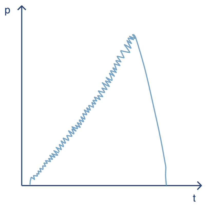
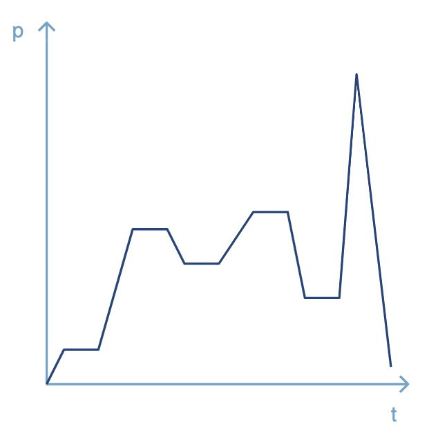
Depending on the pressure generation variant, different pressure curves can be designed. Depending on the test requirement, one variant is more suitable than the other. We work together with our customers to find the best solution. The differences can be easily explained using an example of a burst pressure test. Below are two sample sketches. On the left side, the pressure is generated with a high-pressure pump (HP pump) and you can see the pump operating with its deflections. However, a pump is difficult to regulate and can therefore only be programmed to a limited extent. On the right, you can see a regulated pressure curve. A hydraulic pressure intensifier can, for example, approach various pressure points, hold the pressure there for a programmed time and then precisely control the next point.
The components of our customers are constantly evolving and we support research and development across many industries. Therefore, we continuously invest in our test bench technology to offer state-of-the-art testing solutions.

